Intake air temp sensor (iat) 12. You can poke wires into the afm connector, or you can cut and splice.

wiring gm/aem map & gm/aem iat sensors ClubLexus Lexus Forum Discussion
Having the iat within the maf housing is very convenient.

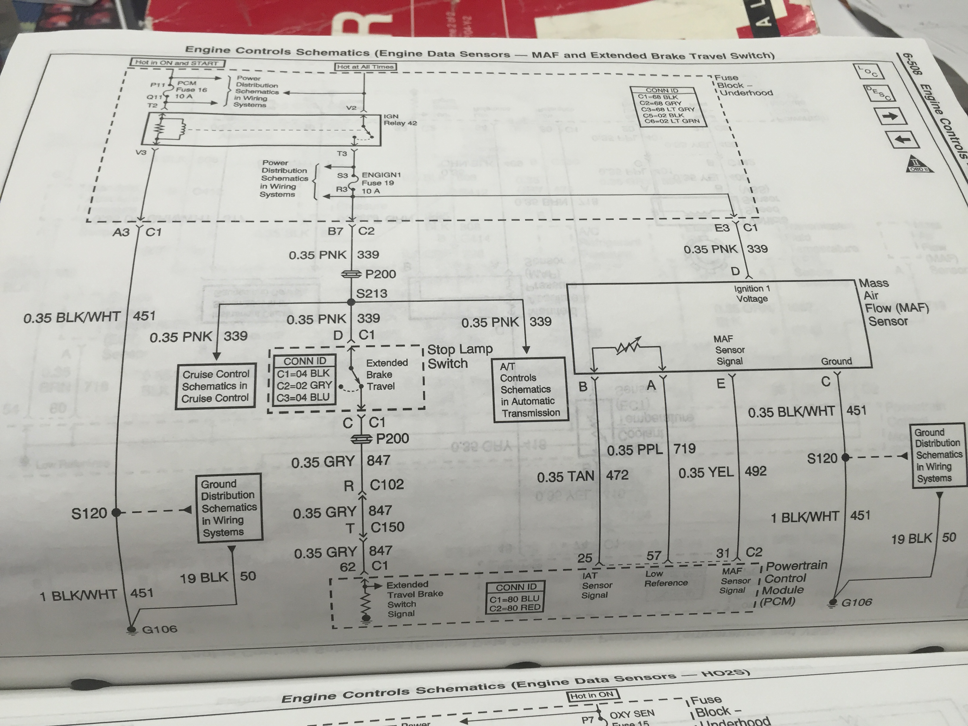
Gm iat sensor wiring diagram. If it is ~zero, your wiring is still shorted. The second picture is the wiring diagram for the maf/iat assembly. Most gm mafs today have 5 wires, since they incorporate the iat sensor these days.
If you want to make the switch to run a sd (speed density) setup but aren't sure how to wire in your iat your in the right place. I personally have not connected one of these chips to a tahoe.what i can provide you with, is the connector diagram so you know exactly what wires you need to splice in to. Simply wire a gm open element iat sensor into your factory wiring harness at the afm connector.
This is a write up on how to wire in a gm iat (intake air temp) sensor in a 2g and logging it using dsmlink v3. Coolant temp sensor (ect) 9. Throttle position sensor (tps) 6.
Mass airflow sensor (maf) 4. Disconnect the db37 at megasquirt, and check the resistance from harness pin 20 to ground pin 7 (i.e., the iat sensor reading), if it is between 100000 and 200 ohms, you should get a temp reading. Use this sensor to input intake air temperature iat to your aem ecu.
Maf sensor connector pinout on l, l, l engines. If your iat (intake air temperature) sensor doesn't respond, you can: But, it doesn't mean connection between the cables.
The second picture is the wiring diagram for the maf/iat assembly. There are two points on the mspnp where you can connect an iat sensor. What is wiring diagram for air flow sensor?
This makes the procedure for assembling circuit. Since you'll also need to connect a map sensor to go sd you'll also. By continuing to use this site you consent to the use of cookies on your device as described in our cookie policy unless you have disabled them.
Avalanche, sierra, silverado, c&k series, pin, wire color, circuit no. Locating the iat sensor on a chevy tahoe 2008 yes. On the other hand, this diagram is a simplified version of this arrangement.
Its extra two wires are used for the internal iat sensor. At times, the cables will cross. Wire one lead of the gm sensor to the brown wire at the afm connector, and the other lead of the gm sensor to the yellow wire at the afm connector.
Use the dtm version for most manifolds. The air intake temp sensor is built into the mass air flow sensor on the air filter box. According to previous, the lines at a mass air flow sensor wiring diagram represents wires.
Injunction of two wires is usually indicated by black dot in the intersection of 2 lines. There's only 3 for the maf itself: Map sensor • 3.1l / 3.4l serpentine belt routing diagram
Wiring & logging a gm iat sensor. There'll be main lines which are represented by l1, l2, l3, and so on. Maf sensor connector pinout on l, l, l engines.

I have a 2011 Yukon Denali. I don't have the wiring diagram but I need to identify the two wires

P0113 Honda Crv 2005 Mansoor ahmad auto electrician efi&ac Lainey Love

What two wires go to maf/iat sensor on a 5 wire plug

[DIAGRAM] Iat Sensor Wiring Diagram Gmc 2008 FULL Version HD Quality Gmc 2008 CFLWIRING

Which specific wires are the IAT sensor wires on a 2012 Camaro 3.6L? What position on the MAF

Iat Sensor Wiring Diagram Gmc 2008 Wiring Diagram

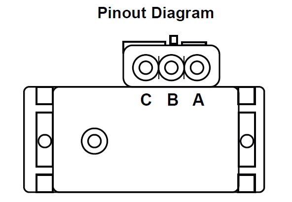
Wiring your GM Map Sensor / IAT Sensor for use with a 'CSL' clone ECU ECUWorx

What two wires do i hook the chip to on the iat sensor on 2005 gmc canyon

Iat Sensor Wiring Diagram Gmc 2008 Wiring Diagram

Repair Guides

Where do I locate the IAT sensor on a 2001 chevy suburban

Repair Guides

confused as hell with GM IAT wiring NASIOC

Repair Guides

I am installing a performance chip on my 2005 GMC Sierra 2500HD 6.0L which requires a connection

5 Wire Maf Sensor Wiring Diagram Mass Air Flow Sensor Wiring Diagram Fuse Box And Wiring

2b) GM MAP and IAT Sensors (aka Speed Density) Current Version = 2.0

Repair Guides

Iat Sensor Wiring Diagram Gmc 2008 Wiring Diagram


